|


| |
GN Electric Operations continued
OPERATION
HOW TO OPERATE YOUR ELECTRIC
LOCOMOTIVE
A. PREPARING TO START
1. Be certain all control handles are in the Off
position with the exception of the Selector Handle which has
no Off position.
2. Close BATT. DS switch.
3. Press PAN UP button for pantograph desired if
pressure is still maintained in control reservoir. In the
event sufficient pressure is not available, raise
pantograph by operating pantograph hand pump, adjacent to
starting position, until sufficient pressure has built up
to release the pantograph locking down device.
4. At Control Compartment, No. 1 end, check to see if
the 45 V. REG. 1 circuit breaker is closed.
5. At Control Compartment, No. 2 end, check to see if
the following circuit breakers are closed:
a. MA1 FIELD, MA2 FIELD
b. SGR FIELD
c. TRANS. PUMP
d. MG SET CONT'L
e. AUX. CONT'L
f. 46V REG 2
B. STARTING
I. At the starting position press the following buttons:
a. No. 1 COMP—starts—Compressor No. 1 end
b. No. 2 COMP—starts—Compressor No. 2 end
c. No. 1.MA Set—starts—Motor Alternator No. 1 end
d. No. 2 MA Set—starts—Motor Alternator No. 2 end
e. No. 1 MG Set—starts—Motor Generator No. 1 end
f. No. 2 MG Set-starts—Motor Generator No. 2 end
Page 93
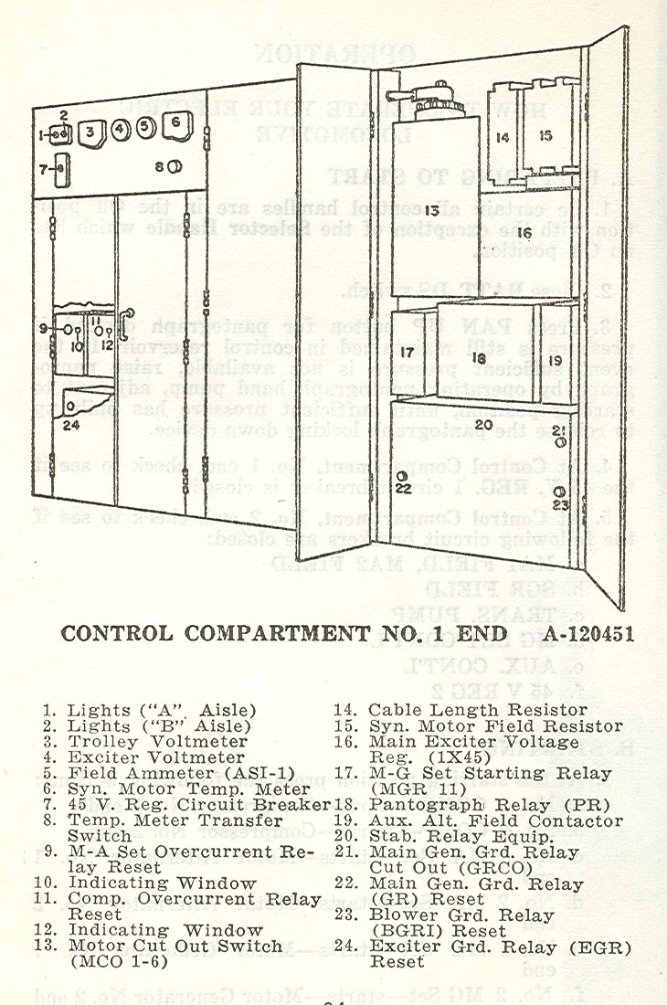
Control Compartment No. 1 End -
Plate A-120451
Page 94
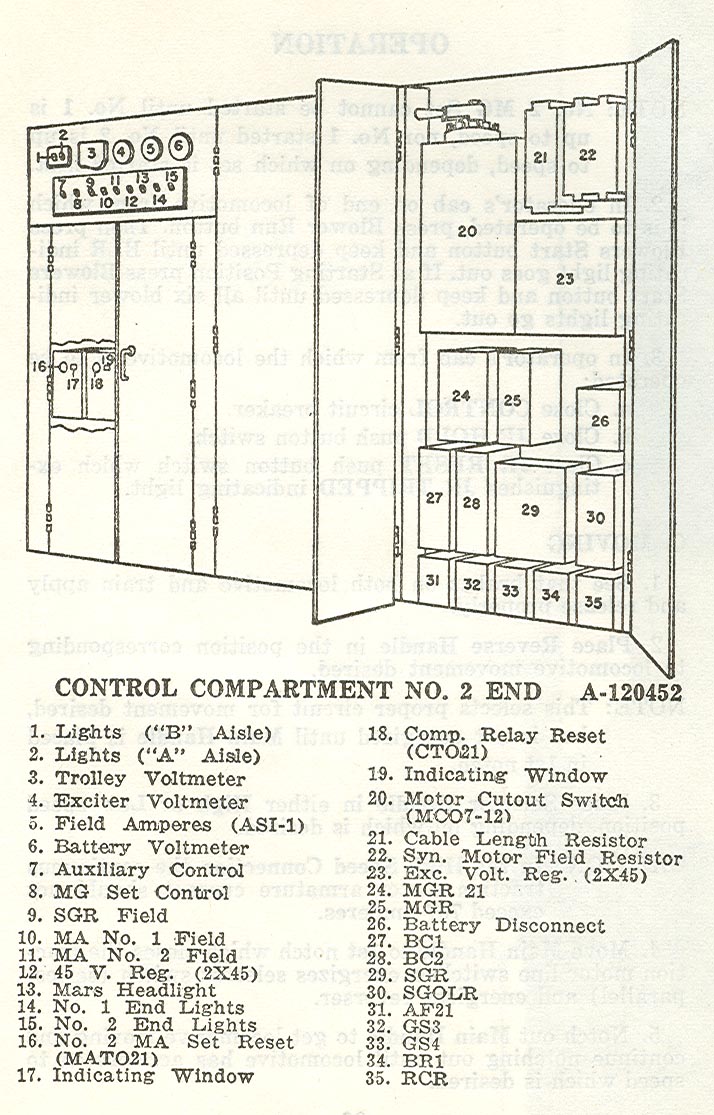
Control Compartment No. 2 End -
Plate A-120452
Page 95
OPERATION
NOTE: No. 2 MG Set cannot be started until No. 1 is
up to speed, nor No. 1 started until No. 2 is up
to speed, depending on which set is started first.
2. In operator's cab on end of locomotive from which
it is to be operated, press Blower Run button. Then press
Blowers Start button and keep depressed until BLR
indicating light goes out. If at Starting Position press Blowers
Start button and keep depressed until all six blower
indicating lights go out.
3. In operator's cab; from which the locomotive is to be
operated:
a. Close CONTROL circuit breaker.
b. Close JR HOLD push button switch.
c. Close JR RESET push button switch which extinguishes
JR TRIPPED indicating light.
C. MOVING
1. See that brakes on both locomotive and train apply
and release properly.
2. Place Reverse Handle in the position corresponding
to locomotive movement desired.
NOTE: This selects proper circuit for movement desired,
but is not energized until Main Handle is placed
in 1st notch.
3. Place Selector Handle in either High or Low speed
position, depending on which is desired.
CAUTION: In the High Speed Connection the continuous
traction motor armature current should not
exceed 767 amperes.
4. Move Main Handle to 1st notch which closes the
traction motor line switches, energizes selector switch
(series-parallel) and energizes reverser.
5. Notch out Main Handle to get locomotive moving and
continue notching out until locomotive has accelerated to
speed which is desired.
Page 96
 
 
|