|


| |
GN Electric Operations continued
DESCRIPTION
EMERGENCY CONTROL DEVICES
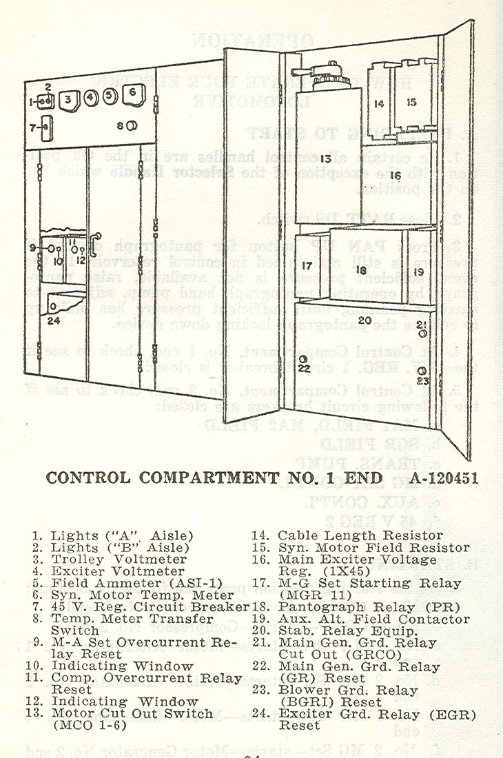
PANTOGRAPH RELAY (PR)
This relay (See Plate
A-120451) is the only primary
circuit protection provided, consequently no restraining
devices must be put on any contacts nor any adjustments
attempted except by authorized personnel.
Serious damage to equipment due to a fault is
prevented by the pantograph relay, which is provided with
five contacts to perform its assigned functions in the
following sequence.
1. "A" contact removes the secondary load and lights
the PR TRIP indicating light at the operator's
position. If this does not clear fault, PR continues to
operate and:
2. "B" contact applies a ground to the pantograph,
and should trip track breakers.
3. "C" contact lowers the pantograph after the power
has been removed by the track breakers.
"D" contact prevents the relay from operating on surge
currents caused by the pantograph momentarily losing
contact with the trolley wire.
If contact "A" functions, the relay may be reset by
returning the Main Handle and Separate Excitation
Handle to their OFF positions and pressing the JR reset
button, which resets both the JR breakers and PR relay.
When PR is reset, the locomotive may be moved, and if
the relay does not trip, the operator may proceed with
normal operation.
A full sequence of contact operations requires the
relay be manually reset.
Page 89
DESCRIPTION
NOTE: If at all possible, the cause of the fault should
be determined and corrected and the relay manually reset.
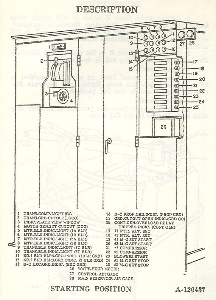
TRANSFORMER GROUND CUTOUT SWITCH (TGCO)
In the event the PR relay partially or completely trips
due to a secondary ground, the operator should try
resetting it and starting until it is certain a permanent
ground is present.
Then open the Transformer Ground Cutout Switch (See
Plate A-120437) which
places a high resistance in series
with the transformer secondary to ground and lights
the GRDCO indicating light at the starting position. The
operator can then proceed and operate normally, but must
be alert for possible trouble which will be indicated by
excessive beat, smoke, fire, etc.
EMERGENCY GROUND PUSH BUTTON
In the event an emergency occurs which is apparently
not being cleared by automatic devices, the EMER. GRD.
SWITCH can be operated which will ground the
pantograph and trip the track breaker.
MAIN GENERATOR GROUND RELAY (GR)
When the main generator ground relay (GR) functions,
it opens the JR circuit breaker removing power from the
traction motors and lights the JR TRIP indicating light
at operator's position and the PROP GRD indicating
light at the starting position.
MAIN GENERATOR GROUND RELAY CUTOUT (GRCO)
GRCO is provided in No. 1 end control compartment
(See Plate A-120451), to
cut out the ground relay (GR)
and continue operation.
When GRCO button is pulled, in addition to cutting out
the relay (GB) it also lights the GRD CO indicating
light at the starting position which provides a warning
that operation is being undertaken with a protective
device out of the circuit.
Page 90
DESCRIPTION
MAIN GENERATOR CUTOUT (GCO)
In the event a fault develops in one of the main
generators a switch (See Plate A-120437) is provided at the
starting position to cut out the generator concerned.
NOTE: It is necessary to remove the load from the
generators before cutting them out.
MOTOR CUTOUT SWITCHES (MCO)
1. If it becomes necessary to cut out one or more pair
of traction motors, due to a fault, MCO switches (See
Plates A-120451 and A-120452) are provided in both
operators' cabs for this purpose.
NOTE: Power must be removed from traction motors
before they can be cut out.
2. The MCO switches with their respective cutout
combinations are as follows:
MCO 1-6 (No. 1 END)
ALL IN
1 and 2
3 and 4
5 and 6
1-2-3 and 4
3-4-6 and 6
1-2-5 and 6
ALL OUT
MCO 7-12 (No. 2 END)
ALL IN
7 and 8
9 and 10
11 and 12
7-8-9 and 10
9-10-11 and 12
7-8-11 and 12
ALL OUT
BLOWER CUTOUT SWITCHES
Each traction motor blower and transformer blower is
provided with a large enclosed switch to cut it out of the
circuit in case of a fault. There are three of these switches'
in the No. 1 end of the motor generator compartment and
three in the No. 2 end, which allow each blower to be
cut out separately.
Page 91
DESCRIPTION
STARTING GENERATOR CUT OUT (SGCO)
These switches are located above the motor alternator
sets in the nose compartments on both ends of the
locomotive.
It is preferable to remove the load from the starting
generator at fault before it is cut out.
LOCOMOTIVE OVERSPEED
When the locomotive exceeds 62 mph the overspeed
whistle switch (OSW) is actuated which causes the
overspeed whistle to blow. At 65 mph the overspeed power
relay (OSPR) will be energized, the JR circuit breakers
opened and a full service application of air brakes be
initiated.
After the JR circuit breakers are tripped it will be
necessary to return all control handles to OFF position
and push the JR RESET push button switch before
starting up again.
ROUND HOUSE COUPLER AND SWITCH
Provision is made to move the locomotive while in the
round house by utilizing an outside D-C power supply,
which can be connected to the Round-House Coupler. Then
by placing the Round-House Coupler Switch (located in
the "A" side of No. 1 end control compartment) in the
down position, power can be supplied to traction motors
No. 1 and No. 2 by placing Main Handle on the controller
in the 1st notch.
Page 92
 
|