|
GN Electric Operations continued
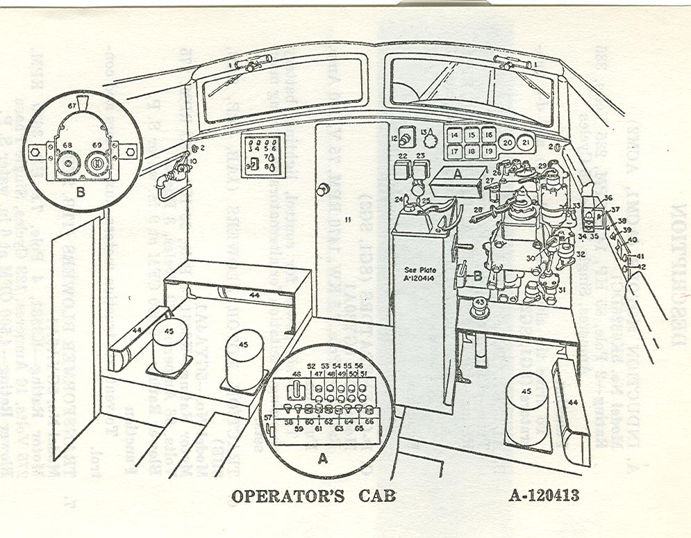
LEGEND FOR OPERATOR'S CAB (Plate A-120413)
1. Windshield Wipers
2. Windshield Wiper Valves
3. Order Light Switch
4. Number Light Switch
5. Marker Light Switch
6. Nose Light
7. Heater Switch No. 1
8. Heater Switch No. 2
9. Htr. and Def. Cir. Br'kr
10. Conductor's Valve
11. Door to Nose Comp't.
12. M-G Set Stop
13. Gage and Instrument Light Rheostat
14. Equalizing Voltmeter
15. Sync. Motor Ammeter
16. Speedometer
17. Generator Voltmeter
18. Field Ammeter
19. Armature Ammeter
20. Main and Eq. Reservoir Gage
21. Brake Cylinder and Brake Pipe Gage
22. Wheel Slip Buzzer
23. Trailer Alarm
24. Overspeed Whistle
25. Signal Whistle
26. Train Control and Safety Control Cock
27. Double Heading Cock
28. Automatic Brake Valve Handle
29. Independent Brake Valve Handle
30. Bell Ringer Valve
31. Reducing Valve
32. Feed Valve
33. Controlled Emergency Cock
34. Self Excitation Button
35. Sep. Excitation Button
36. Horn Button
37. Control Circuit Breaker
38. Order Light Switch
39. Headlight Circuit Br'kr.
40. Htr. and Def. Circuit Breaker
41. Heater Switch No. 1
42. Heater Switch No. 2
43. Sander Foot Switch
44. Heaters
45. Seat Stands
46. Meter Transfer Switch
47. Separate Excitation Light
48. Wheel Slip Light
49. JR Trip Light
50. PR Trip Light
51. Blower Grd. Relay Tripped
52. Hot Transformer Light
53. Blower Stopped Light
54. Overvoltage Relay Trip Light
55. Batt. Not Charging Light
56. Not Used
57. Push Button Switch Lock
58. Emergency Ground (Locked)
59. Pantograph Down
60. Rear Pan Up
61. Front Pan Up
62. Multiple Unit M-G Stop
63. Blowers Start Push Button Switch
64. Blowers Run Push Button
65. JR Hold Push Button
66. JR Reset Push Button
67. Mars Headlight Switch
68. Jog Switch
69. Oscillating Motor Switch
Page 85
DESCRIPTION
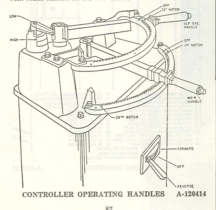
CONTROLLER OPERATING HANDLES
A. MAIN HANDLE
An Off position and 39 control notches are provided
on the Main Handle. The 1st notch establishes connections
for the direction of locomotive movement selected
and notches 2 thru 39 are for increasing tractive effort; or
in the event that separate excitation has been established,
to act as a control for the condition selected.
B. SEPARATE EXCITATION HANDLE
When separate excitation is desired this handle is
provided to establish that condition at any notch of the Main
Handle. Also, once that separate excitation has been
established, the Separate Excitation Handle can be moved
to provide either braking effort or tractive effort.
C. REVERSE HANDLE
Direction of locomotive movement is determined by this
handle which cannot be moved unless the Main Handle
and Separate Excitation Handle are in Off position and
MUST NOT BE MOVED WHILE LOCOMOTIVE IS IN MOTION.
D. SELECTOR HANDLE
This handle is used to pro-select either the High or Low-
speed connection in which the locomotive is to be operated.
E. INTERLOCKING BETWEEN HANDLES
1. Main Handle
a. Cannot be moved from Off notch unless the Reverse
Handle is in an operating position.
b. Cannot be moved from 1st to Off notch unless the
Separate Excitation Handle is in Off notch.
2. Separate Excitation Handle
a. Cannot be moved from Off position unless the
Reverse Handle is in an operating position and the Main
Handle is in one of its 39 operating notches.
b. Cannot move from 1st to E notch when locking
coil for Separate Excitation Handle is energized.
c. Can move from E to 31st notch and back to 1st
notch when locking coil for Separate Excitation Handle is
energized.
Page 86
DESCRIPTION
d. Cannot move from E notch to Off notch when
locking coil for Separate Excitation Handle is energized.
e. Can move from Off to E notch or from E to Off
notch when Separate Excitation Handle locking coil is
de-energized.
f. Cannot move from E to 1st notch when Separate
Excitation Handle locking coil is de-energized.
3. Reverse Handle
a. Cannot be moved from an operating position to
Off position unless the Main Handle and Separate
Excitation Handle are in the Off position.
4. Selector Handle
a. Can be moved from one position to another only
with Main Handle in the Off notch.
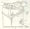
Controller operating handles -
Plate A-120414
Page 87
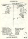
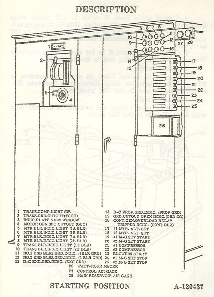
Electrical Cabinet in Starting Position -
Plate A-120437
Page 88
 
 
| 